Software Overview
This is computationally heavy software, it is designed to be run unattended on remote machines, it doesn’t (yet) have a Graphical User Interface, it isn’t even clear that such a graphical interface would actually do anything useful.
So the toolchain consists of a collection of related command-line tools and libraries supporting the workflow described below.
Files and Folders
Each building ‘plot’ is represented by a folder in the filesystem, so multiple adjacent plots are represented by multiple folders in a project folder.
Typical files are:
- Patterns configuration. This is an optional file used to override default
design Patterns used as a ‘value’ component of the fitness criteria. This file only needs to contain the parameters that need to be altered, and can exist in the project folder or the plot folder or both. Adding a
spaces:key to this file switches on ‘programme-driven’ fitness: instead of letting room types and counts emerge from the original site-driven scoring, you define an exact list of rooms (custom codes, target sizes, required adjacencies), and the building is evolved to fit that specific programme. This is also how the software now handles building types beyond ordinary housing — a shop or a workspace is just another room type in the programme. - Costs configuration. This is another optional file used to override default ‘costs’ per m² that form the other half of the fitness criteria. Configuration is inherited in a similar way to the patterns configuration — see Costing, and where building services fit for what’s actually priced, and what isn’t yet.
- Occlusion field. This is also optional, though without it the building would be created in an empty environment as if in a flat desert with a distant horizon. If you are using the Homemaker queue manager this is generated as part of the process, picking up any external objects specified in .walls files in the project folder. This is also what lets multiple buildings shape each other as they evolve together — see Growing buildings in a daylight field for what that feedback loop actually does.
- Building geometry files. Evolution proceeds as a population of individuals, although initially there may be a single file containing just the location of the plot boundary. These files each contain a complete description of the steps necessary to construct the three dimensional geometry of an individual instance of the building.
Crossover and Mutation
Population diversity is created through crossover and mutation, typically two individuals are selected to exchange a part of their genetic code, creating two new files. Mutation is random and is applied in addition to Crossover.
Note that crossover and mutation happen to individuals without reference to the fitness environment.
Fitness
Each individual is ‘scored’ based on their fitness in the environment defined by the configuration, these scores are cached as additional files in the folder so they don’t need to be recalculated for individuals that survive into the next generation.
Selection
Selection is based entirely on fitness scores, and individuals are removed from the population by deleting files. Selection doesn’t necessarily just retain the highest scoring individuals as this may not maintain diversity.
Iteration
This Crossover, Fitness, Selection process repeats for a fixed number of generations or until stopped manually.
Reiteration
It needs to be emphasised that in optimisation terms, the result of this process is a ’local minima’, the resulting building is a good fit for the environment such that there are no further small changes likely to improve fitness. This doesn’t mean that the result is ‘perfect’, running the entire process from the beginning may produce different ’local minima’ and these also can be explored.
More than this, each building is evolved within an environment of surrounding buildings. If the project involves creating more than one building then this environment will change as the buildings change, so further iterations will be required.
Generation of 3D geometry
The population individuals contain ‘genetic code’ that defines the steps needed to construct the building geometry in three dimensional space. This genetic code doesn’t resemble an actual building in any way, so further steps are needed to unfold something that looks like a building:
- Each step of the construction, a wall, ceiling, roof, stair etc… is
described in an intermediate format and written as a separate
.moliorfile. - A tool from the Molior module takes each of these components and turns them into DXF fragments of 3D surface geometry.
- Another tool from the File::DXF module joins these together into a single DXF file.
- Optionally other tools from File::DXF can be used to create Collada files for importing into Blender or Sketchup, STL files for 3D printing, or RIB Renderman files.
Alternatively there is partially implemented IFC (Industry Foundation Classes) export available using the experimental File::IFC module.
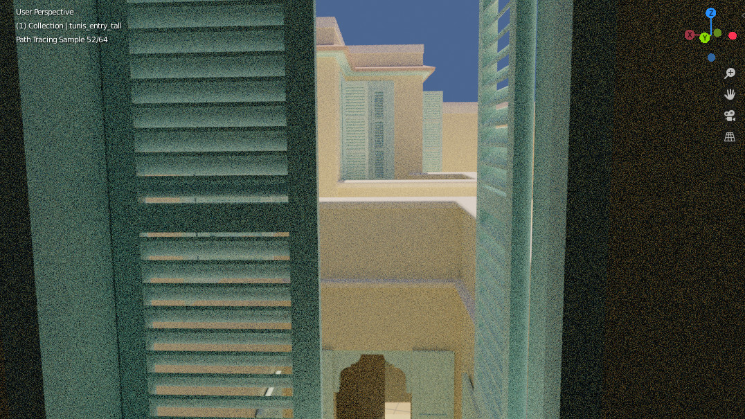
Collada model rendered in Blender:
Current development
A from-scratch Python rewrite of the evolution engine is in active development, alongside the Perl toolchain described above — see Related tools for what’s changing and why. Everything above is a fully automated, hands-off process; for an interactive, human-driven design tool built on the same form language and IFC output, see Homemaker add-on and homemaker-web. For the practical, step-by-step version of everything above, see the Homemaker walkthrough; for a plain feature list, see Features.
Last updated 29 March 2020.